Receiver
11 Mar 2019 Revised by Kazuyuki Takeda 8 Mar 2019 document created by Kazuyuki Takeda
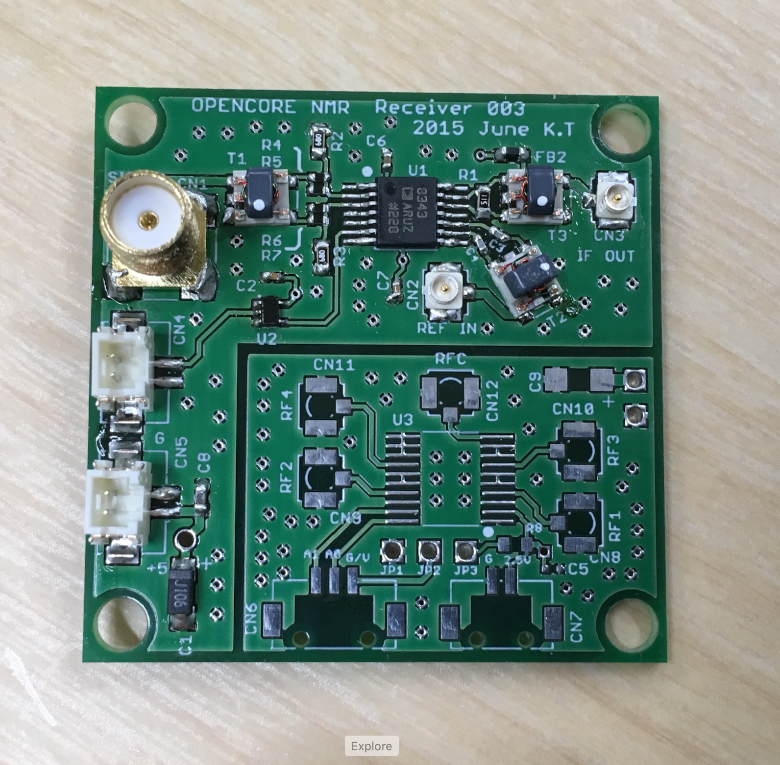
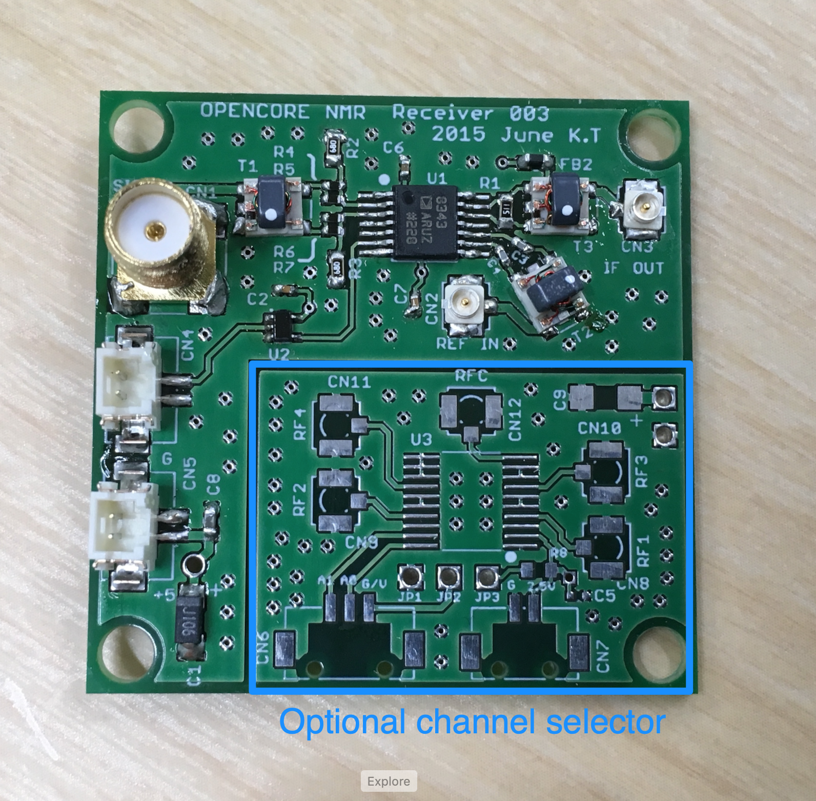
Note that the right bottom part of the board serves for an optional receiver-channel selector. That is, you may leave this part blank, like the one in the photo shown here. In our lab we make fully use of it. How to built/use the channel selector will be described elsewhere.
Board Design
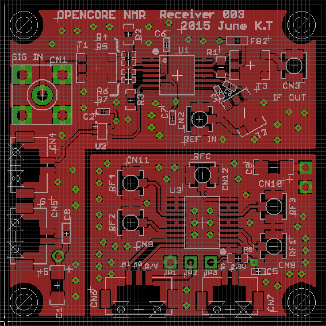
- The board was designed on EAGLE 6.2.0 Professional
- There are 4 layers. That is, in addition to the top and bottom layers, the board has two inner layers.
EAGLE schematic and board files
- Schematic: rcvr003.sch
- Board: rcvr003.brd
Gerber files
- rcvr003.cmp (Component side pattern)
- rcvr003.plc(Component side silkscreen)
- rcvr003.sol(Solder side pattern)
- rcvr003.stc(Component side solder resist)
- rcvr003.sts(Solder side solder resist)
- rcvr003.2l(2nd (inner) layer pattern)
- rcvr003.3l(3rd (inner) layer pattern)
- rcvr003.out(outline)
- rcvr003.dri (drill list)
- rcvr003.drd(drill data)
Note: The component side mean the top (1st) layer, while the solder side does the bottom layer.
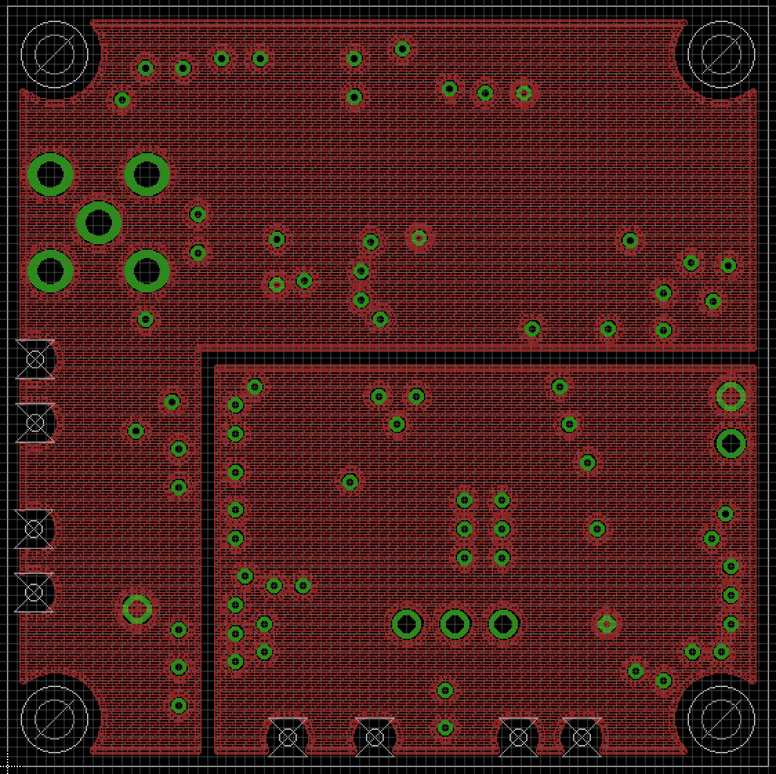
Component layer
2nd (inner) layer
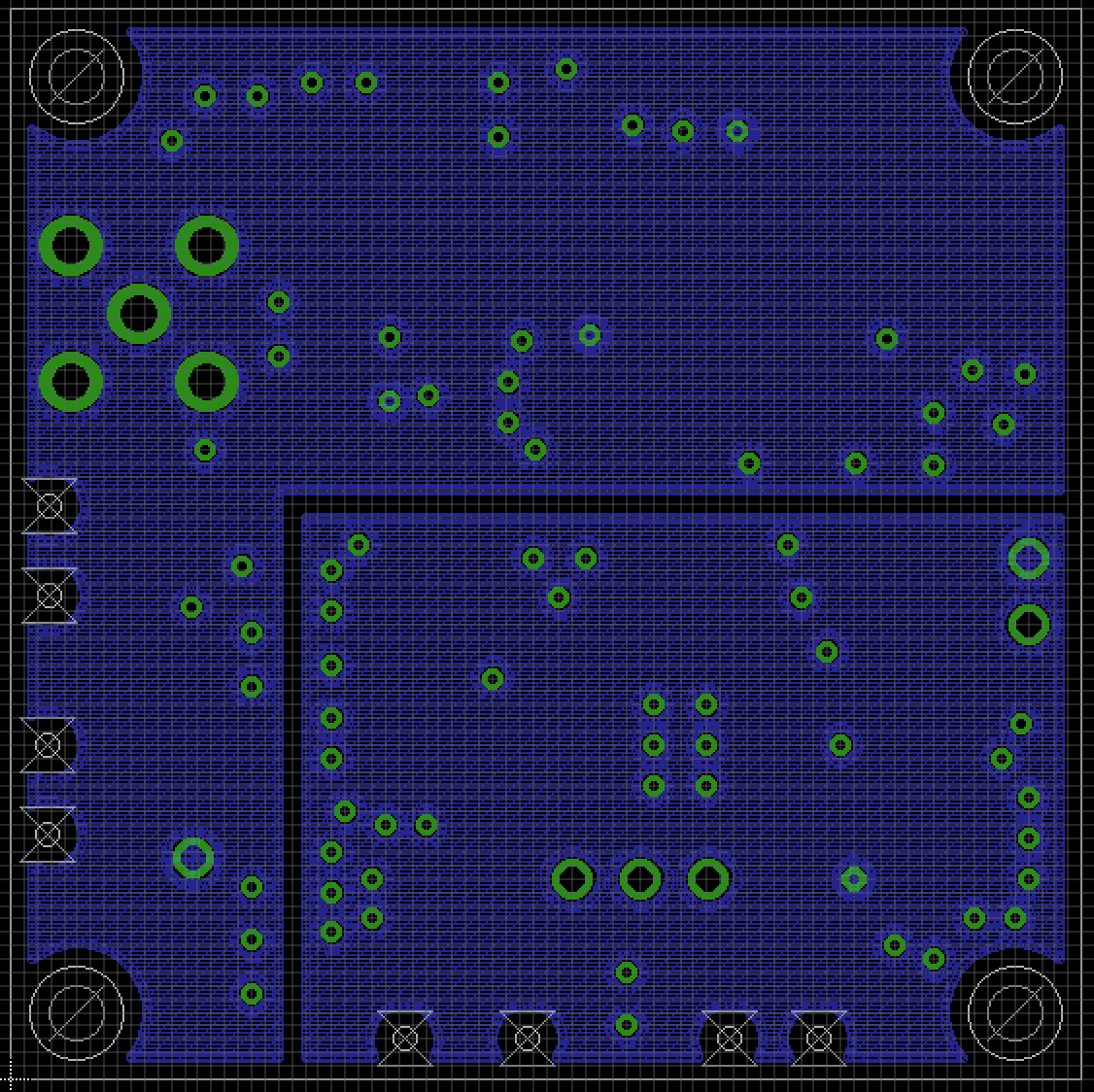
3rd (inner) layer
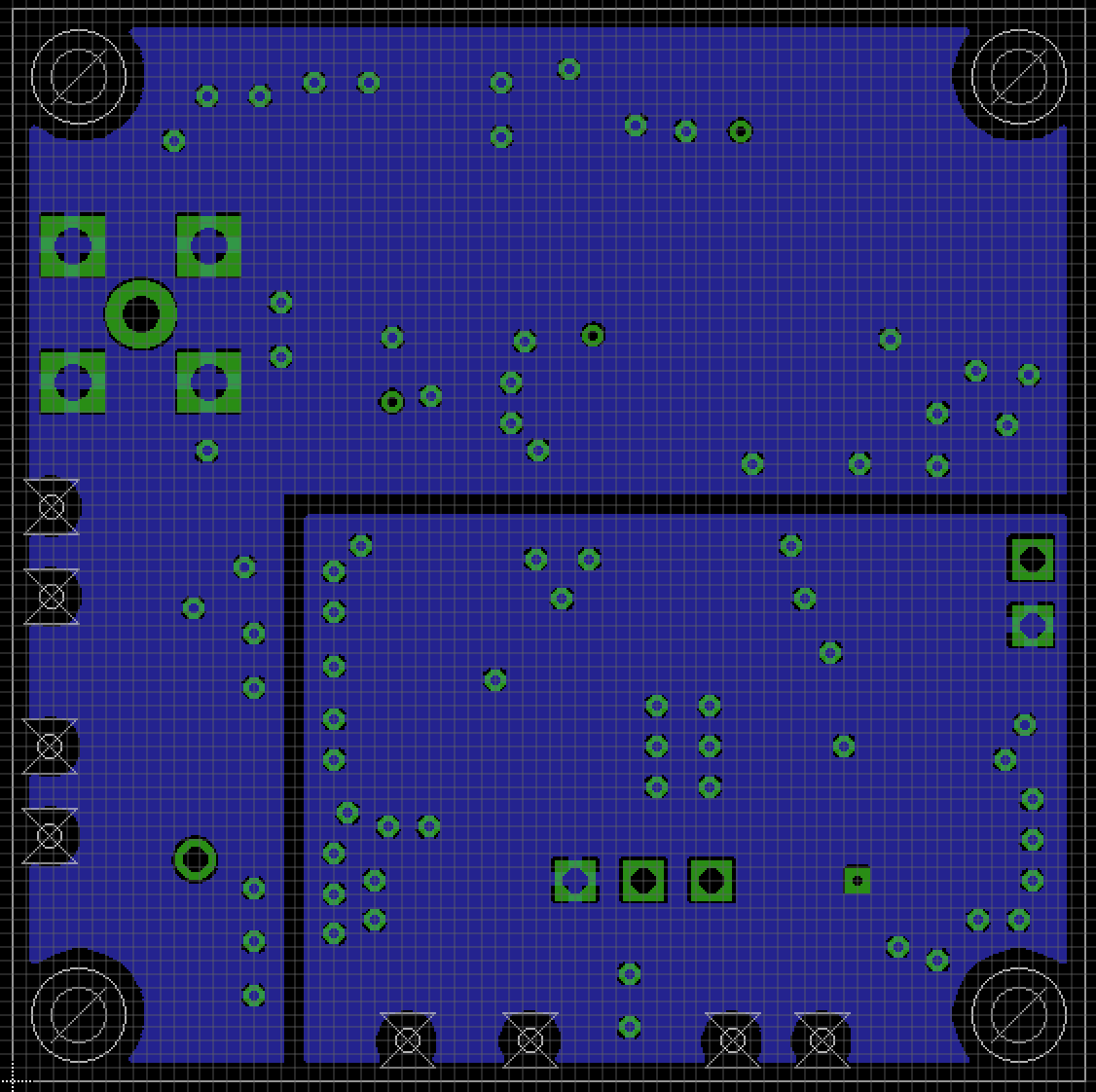
Bottom layer
Parts List
| Part | Value | Device | Package | Description |
|---|---|---|---|---|
| C1 | 10u | Tantalum Capacitor | 3216 (polar) | |
| C2 | 0.01u | Capacitor | 1005 | |
| C3 | 0.1u | Capacitor | 1005 | |
| C4 | 0.1u | Capacitor | 1005 | |
| C5 | 0.1u | Capacitor | 1005 | |
| C6 | 0.1u | Capacitor | 1005 | |
| C7 | 0.01u | Capacitor | 1005 | |
| C8 | 0.01u | Capacitor | 1608 | |
| C9 | 10u | Tantalum Capacitor | 3216 (polar) | |
| CN1 | SMA Straight PCB Socket | 5-1814832-1 (TE Connectivity) | ||
| CN2 | U.FL-R-SMT | HIROSE | ||
| CN3 | U.FL-R-SMT | HIROSE | ||
| CN4 | DF13-2P-1.25V | 1.25mm Pitch Miniature Crimping Connector | HIROSE | |
| CN5 | DF13-2P-1.25V | 1.25mm Pitch Miniature Crimping Connector | HIROSE | |
| CN6 | DF13-3P-1.25V | 1.25mm Pitch Miniature Crimping Connector | HIROSE | |
| CN7 | DF13-2P-1.25V | 1.25mm Pitch Miniature Crimping Connector | HIROSE | |
| CN8 | U.FL-R-SMT | HIROSE | ||
| CN9 | U.FL-R-SMT | HIROSE | ||
| CN10 | U.FL-R-SMT | HIROSE | ||
| CN11 | U.FL-R-SMT | HIROSE | ||
| CN12 | U.FL-R-SMT | HIROSE | ||
| FB2 | 30 Ohm @ 100 MHz | MPZ1608S300A | 1608 | Ferrite bead (TDK) |
| R1 | 510 | Resistor | 1608 | |
| R2 | 68 | Resistor | 1608 | |
| R3 | 68 | Resistor | 1608 | |
| R4 | 10 | Resistor | 1005 | |
| R5 | 10 | Resistor | 1005 | |
| R6 | 10 | Resistor | 1005 | |
| R7 | 10 | Resistor | 1005 | |
| R8 | 100 | Resistor | 1608 | |
| T1 | TC4-1W+ | AT224 | RF transformer (Mini Circuits) | |
| T2 | TC1-1-13M+ | AT224 | RF transformer (Mini Circuits) | |
| T3 | TC4-1W+ | AT224 | RF transformer (Mini Circuits) | |
| U1 | AD8343 | |||
| U2 | MC74VHC1G04 | Logic Inverter | ||
| U3 | ADG904 | TSSOP |