10 MHz Clock
14 Mar 2019 Kazuyuki Takeda
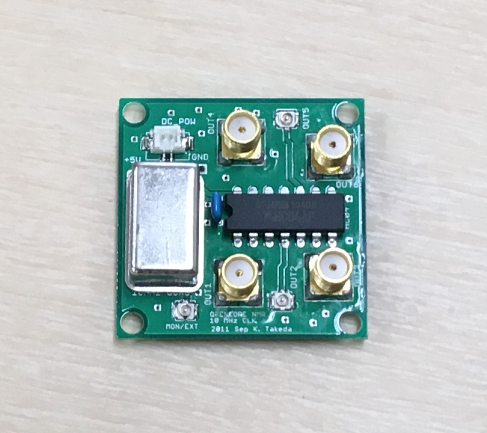
This board generates a clock signal at 10 MHz. On the board, the clock signal is fan-out into several ports. The 10 MHz clock signal is required for the mother board. as well as 1 GHz clock module, to be described in due time.
Board design
- The board was designed on EAGLE 6.2.0 Professional
- There are 2 layers, the top and the bottom layers.
EAGLE schematic and board files
- Board: 10MCLK02.brd
Gerber files
- 10MCLK02.cmp (Component side pattern)
- 10MCLK02.plc (Component side silkscreen)
- 10MCLK02.sol (Solder side pattern)
- 10MCLK02.stc (Component side solder resist)
- 10MCLK02.sts (Solder side solder resist)
- 10MCLK02.out (outline)
- 10MCLK02.dri (drill list)
- 10MCLK02.drd (drill data)
Note: The component side mean the top (1st) layer, while the solder side does the bottom layer.
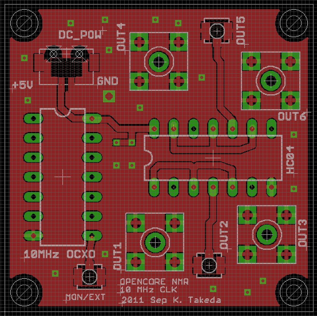
Component side (1st layer)
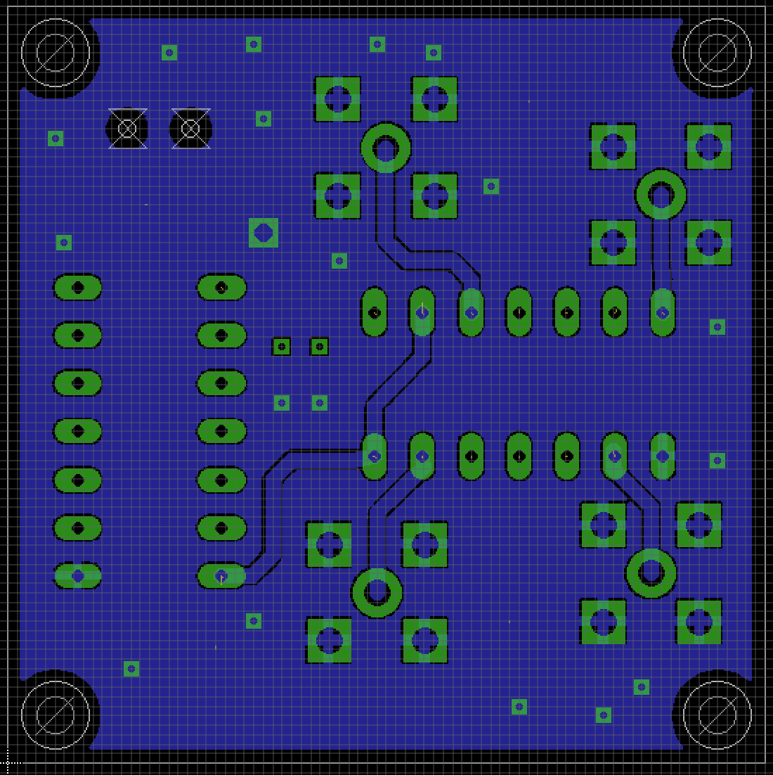
Solder side (bottom layer)
Parts List (TODO)
Part | Value | Device | Package | Description —|—|—|—|— CN | | U.FL-R-SMT | | (HIROSE) CN | | U.FL-R-SMT | | (HIROSE) CN | | U.FL-R-SMT | | (HIROSE) CN | | DF13-2P-1.25V | | (HIROSE) CN | | SMA Straight PCB Socket | | 5-1814832-1 (TE Connectivity) CN | | SMA Straight PCB Socket | | 5-1814832-1 (TE Connectivity) CN | | SMA Straight PCB Socket | | 5-1814832-1 (TE Connectivity) CN | | SMA Straight PCB Socket | | 5-1814832-1 (TE Connectivity) OCXO | | MOFH5200C-10.000 | | (MMD) IC | | HC04 |